

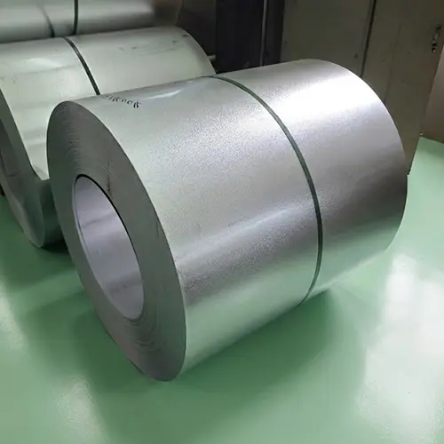
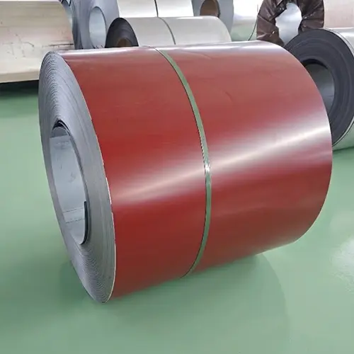

Understanding What Causes Edge Cracks in Color Coated Steel Coil requires analyzing four primary process vulnerabilities. Poor substrate microstructure creates localized stress boundaries along the strip edges. Excessive slitting burrs form micro-fissures during strip shear operations. Improper Peak Metal Temperature (PMT) curing schedules embrittle the coating and underlying metal matrix. Physical handling damage creates mechanical notches that propagate into deep fractures during uncoiling.
Process engineers eliminate these edge defects through three targeted line interventions. Shear clearance calibration minimizes edge strain during trimming operations. Furnace temperature optimization prevents thermal shock and restores coating elasticity. Precision edge deburring systems remove micro-fissures before final curing.
Key Takeaways
- Defects in original steel slabs create initial weak spots along coil edges.
- Rough transport and handling crush coil margins and create sharp surface nicks.
- Incorrect slitting blade clearance damages the metal edge and forms deep micro-cracks.
- Dull cutting knives create sharp metal burrs that concentrate tension stress.
- High oven temperatures make the steel edge brittle and prone to cracking.
- Uneven line roll tension stretches outer coil edges beyond their strength limits.
- Operators prevent cracks by adjusting shear blades and using edge deburring systems.
- Oven baffles ensure uniform heating and protect coating elasticity during curing.
What Causes Edge Wave Cracks in Color Coated Steel Coil: Primary Root Factors

Upstream Metallurgical and Slab Defects
Continuous Casting Corner Cracks
Continuous casting defects in steel slabs frequently initiate severe edge failure during downstream processing operations. Mold powder entrapment and uneven secondary cooling schedules create fine corner cracks on the molten steel slab. These sub-surface micro-fractures survive initial slab reheating furnace operations without scaling away completely.
Hot rolling mills subsequently stretch these original corner cracks along the strip margins. The rolling forces transform small open defects into long longitudinal surface flaws along the strip perimeter. These weak points directly explain what causes edge cracks in color coated steel coil during line tensioning.
Coarse Grain Structure Stress Limits
Non-uniform cooling rates during slab solidification foster excessive columnar grain growth inside the slab corner zones. These large, oriented grains form coarse strip-shaped microstructures along the strip edge during hot strip mill processing. Coarse grain networks significantly lower both the yield strength and fracture stress limits of the base metal.
Mechanical stress concentrates along these weak grain boundaries during active continuous processing. Applied line tension quickly exceeds the low fracture stress threshold of the coarse grain structure. The metal lattice splits along the outer edge boundaries, initiating fine edge tears before coating application.
Mechanical Edge Damage and Handling
Physical Impact During Coil Transport
Improper handling during transit severely compromises coil margins before processing on the color coating line. Heavy forklifts, improper coil hooks, and overhead cranes frequently strike the unprotected outer edges of master steel coils. These violent mechanical impacts crush the strip edges and induce localized cold work hardening.
This mechanical shock alters the localized metallurgical grain structure of the steel sheet. Thorough analysis of what causes edge cracks in color coated steel coil requires evaluating this transportation damage carefully. High uncoiling tension on the production line easily ruptures these pre-stressed, brittle edge sections.
Mechanical Edge Gouges and Nicks
Rough contact with improper floor saddles, rusty transport chocks, and storage racks creates deep mechanical gouges along coil edges. Sharp equipment contact points gouge notch defects deep into the master coil edge profile. These severe surface nicks act as primary stress concentrators under longitudinal mechanical tension.
Tension bridles continuously stretch the damaged steel strip during continuous coating operations. Operational stress concentrates directly at the geometric tip of each mechanical notch defect. The localized strain quickly exceeds the ultimate tensile strength of the material, causing micro-fissures to propagate into visible edge cracks.
Mechanical Stress in Slitting and Trimming
Improper Shear Clearance Ratios
Excessive Clearance Tear Fractures
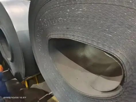
Incorrect shear clearance during slitting operations severely degrades the mechanical integrity of the steel edge. When operators set an excessive horizontal gap between the rotary slitting knives, the steel strip bends excessively before the final fracture occurs. This wide gap prevents a clean mechanical shear along the cut line.
The extreme bending forces create a large plastic deformation zone along the metal margin. The metal tears apart under tensile stress rather than cutting smoothly. This tearing process leaves a rough, stretched edge profile containing deep micro-fractures. Line tension easily opens these tear fractures during downstream color coating processes.
Insufficient Clearance Double Shearing
Setting an overly tight blade clearance introduces a different mechanical defect known as double shearing. Extremely small gaps force the upper and lower slitting knives to compress the steel matrix without immediate fracture. The knives force two distinct shear planes through the thickness of the steel strip.
These intersecting shear paths create a secondary cut lip along the edge margin. The overlapping shear zones create localized material overlap and secondary micro-cracks. These fractured inner boundaries significantly weaken the edge strength. The steel strip fails rapidly when passing through high-tension bridle rolls.
Edge Burr Formation and Wear
Dull Cutter Stress Concentrators
Continuous slitting operations gradually dull the cutting edges of rotary shear knives. Worn blade profiles lose their sharp cutting geometry and apply compressive crushing forces to the strip margins. This mechanical compression pushes excess metal outward, forming a raised metal burr along the bottom corner of the cut edge.
These sharp burrs act as severe geometric stress concentrators. The irregular metal projections concentrate applied mechanical loads along thin microscopic points. Under process tension, stress multiplies exponentially at the root of each burr notch.
Burr Micro-fissure Propagation
Sharp edge burrs contain fine microscopic cracks created during blade impact. Continuous processing lines subject the running steel strip to heavy longitudinal bending and stretching forces. These dynamic line stresses directly act upon the delicate burr roots.
The mechanical tension forces the micro-fissures to expand into the base metal matrix. Small edge imperfections quickly grow into transverse micro-cracks. The growing cracks penetrate deeper into the strip width as the coil moves through the color coating equipment.
Localized Edge Work Hardening
Cold Working Hardening Effects
Mechanical shearing alters the physical properties of the steel strip through intense cold working. The shear blades exert extreme compressive and shearing forces on the narrow zone immediately adjacent to the cut line. This violent deformation rearranges the internal crystal structure of the metal.
The localized steel matrix undergoes rapid work hardening along the edge profile. This cold-worked zone loses ductility and becomes extremely brittle compared to the center of the sheet. The hardened edge cannot absorb normal bending stresses during uncoiling operations.
Edge Residual Stress Strain
Slitting operations lock high levels of residual tensile stress into the cold-worked edge zone. The mechanical shearing action stretches the outer metal fibers beyond their elastic limit while the internal matrix attempts to pull back. This structural imbalance leaves permanent internal tension along the strip perimeter.
Process tension on the coating line combines directly with these pre-existing residual stresses. The combined mechanical strain exceeds the ultimate yield threshold of the hardened edge matrix. The steel edge splits open, forming visible cracks before the strip enters the coating ovens.
Thermal Curing and Coating Adhesion Failure

Curing Temperature and Thermal Strain
Excessive Peak Metal Temperature
High curing temperatures inside the baking oven degrade the mechanical properties of the steel substrate. When the Peak Metal Temperature (PMT) exceeds specified process limits, heat accelerates grain growth along strip edges. Over-baking induces precipitation hardening inside low-carbon steel grades. This thermal condition converts a ductile metal matrix into a brittle structure.
The embrittled edge matrix loses its ability to absorb mechanical stresses during processing. High PMT levels simultaneously decompose organic lubricants within the chemical conversion coating layer. The steel becomes susceptible to micro-fissuring under active line tension. Over-baked strip margins split rapidly when bending around small steering rollers.
Transverse Thermal Gradient Strain
Non-uniform heat distribution across the oven chamber creates thermal gradients between the center and edges of the steel strip. Oven nozzles frequently deliver excessive energy to outer strip perimeters. Thin strip margins heat faster than the center mass. This unequal heat transfer causes differential thermal expansion across the strip width.
The expanding edge zones experience intense compressive stress during heating, followed by tensile stress during forced air cooling. This thermal cycling locks residual strain into the edge crystal lattice. The resulting structural imbalance forces microscopic cracks to open along outer strip boundaries before reaching the recoiler.
Paint Adhesion and Elasticity Deficiencies
Interfacial Substrate Coating Failure
Inadequate adhesion between the primer layer and substrate causes paint film separation under mechanical strain. Insufficient chemical pretreatment leaves residual rolling oils, iron fines, and surface oxides on the strip surface. These surface contaminants prevent strong chemical bonding at the coating-substrate interface.
Weak interfacial bonds permit microscopic gaps to form whenever the coil undergoes bending forces. Longitudinal line tension forces the paint layer to peel away along compromised edge boundaries. This delamination concentrates mechanical stress directly onto the steel substrate, accelerating visible edge cracking during uncoiling operations.
High Film Thickness Flexibility Loss
Excessively thick paint applications reduce the mechanical flexibility of the cured organic film. Coating applicators occasionally apply extra paint along strip edges due to fluid surface tension and edge-bead effects. This heavy paint film cures into a thick layer with minimal strain tolerance.
Thick paint films exhibit lower elongation capabilities than properly calibrated thin coatings. Bending stresses on bridle rolls quickly exceed the stretch capability of the heavy paint film. The rigid outer coating ruptures first, creating sharp microscopic edge cracks that propagate into the base metal sheet.
Line Tension and Roll Alignment
Asymmetric Strip Tension
Bridle Roll Edge Over-stretching
Mechanical misalignment along bridle rolls creates an uneven tension profile across the running steel strip. When bridle rolls tilt away from a parallel orientation, the mechanical load concentrates heavily along one edge of the sheet. This uneven distribution forces the longer travel side to absorb localized tensile forces beyond normal line parameters.
The excessive edge tension stretches outer metal fibers past their yield strength limits. Steel edges already suffering from slitting burrs or thermal embrittlement fail rapidly under this localized overload. Microscopic cracks form immediately as the over-stretched strip margin wraps around high-friction bridle surfaces.
Steering Roll Correction Stress
Steering rolls continuously adjust strip alignment to prevent camber and tracking errors on high-speed continuous coating lines. Rapid angular steering adjustments pivot the moving strip across its center axis. This sudden pivoting action creates sharp transverse shear stresses along the outer edges of the steel coil.
Frequent steering corrections subject the strip edges to aggressive lateral bending strains. The outer edge on the corrective pivot side experiences sudden spikes in longitudinal tension. Repeated steering adjustments fatigue the vulnerable edge matrix, causing fine longitudinal micro-fissures to propagate into visible edge cracks.
Winding and Coiling Tension
High Recoil Tension Shear
Recoilers maintain tight tension profiles to build stable, compact color-coated steel coils. Excessive recoil tension generates extreme radial compression and circumferential shear forces within the inner coil wraps. These high winding stresses pull tightly against the outer margins of the thin steel sheet.
The combination of severe circumferential shear and high mechanical tension forces existing micro-defects to split open during coiling operations. Cold-worked edge zones cannot stretch to accommodate this intense winding load. The rigid steel lattice ruptures, producing sharp edge cracks along the finished coil profile.
Edge Strain During Uncoiling
Uncoiling equipment applies high braking torque to maintain strip stability at the line entry section. Rapid acceleration or uneven uncoiling tension creates violent mechanical shock waves along the unspooling strip margins. These dynamic operational forces concentrate heavy strain on the outer edges of the unwinding steel sheet.
Pre-existing edge defects from transportation damage or slitting operations act as immediate failure initiation sites during uncoiling. The heavy mechanical strain pulls open dormant micro-fissures as the steel unwraps from the master coil. The steel edge tears apart instantly before the strip even reaches the chemical pretreatment section.
Process Optimization and Prevention Strategies
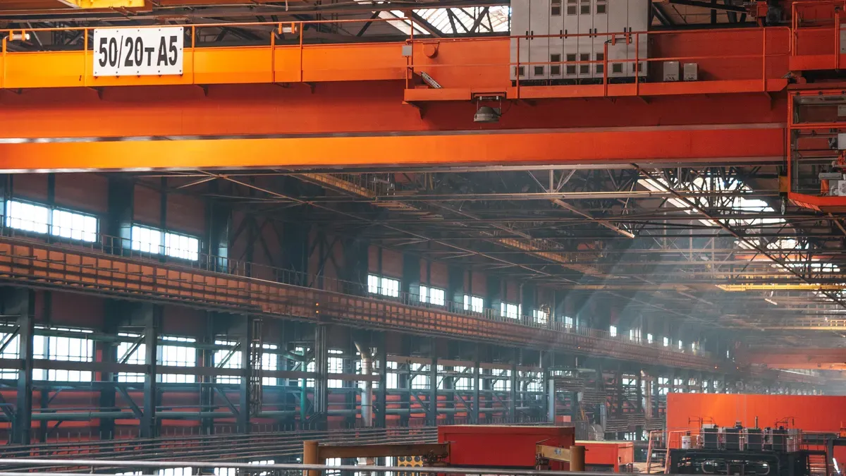
Engineering teams prevent edge cracking through systematic process modifications across the continuous line. Implementing precise operational parameters removes physical defects and thermal imbalances.
Precision Slitting Protocols
Blade Clearance Calibration
Proper blade clearance settings protect the structural integrity of the steel edge during shear operations. Plant technicians calculate horizontal knife gaps based on total sheet thickness and substrate hardness. Refined cutting methods reduce material scrap and eliminate production stoppages due to rework.
recommended clearance = sheet thickness x clearance coefficient
| Substrate Type | Clearance Coefficient Range | Target Edge Profile |
|---|---|---|
| Soft Low-Carbon Steel | 0.06 – 0.08 | Smooth Sheared Depth |
| High-Strength Steel | 0.08 – 0.12 | Clean Fracture Zone |
Precision Edge Deburring Systems
Mechanical deburring units treat the cut edge immediately following the slitting station. High-speed abrasive wheels remove raised metal projections before micro-fissures propagate into the sheet center.
- Motorized edge-trimmers grind away residual metal burrs along both strip margins.
- In-line inspection sensors verify edge smoothness before the strip enters the coating room.
Thermal and Line Parameter Calibration
Edge Baffle Adjustment for Uniform PMT
Adjustable mechanical baffles shield outer strip margins from direct burner flame contact inside the oven chamber. Baffles regulate localized air currents to balance heat absorption across the entire strip width.
A uniform temperature distribution during the curing process is critical. Uneven heating causes the resin to cure at different rates, leading to defects such as warping, residual stress, and inconsistent mechanical properties. Optimizing the heating channels ensures each section cures under nearly identical conditions, thereby improving quality and reducing defects.
Optimized Line Speed and Bake Curves
Process controls match burner line temperatures directly with production line speeds. Operators adjust tunnel airflows to establish a gradual thermal heating profile.
Optimizing surface cooling temperatures in processing tunnels reduces cutting waste by up to 40%. Correct temperature control allows higher processing speeds, increasing total line throughput by up to 35%. Understanding what causes edge cracks in color coated steel coil helps operators set stable thermal baking curves.
Substrate and Coating System Matching
Ductile Base Metal Specification
Quality control teams select fully killed, extra-deep drawing steel grades for aggressive roll forming applications. Fine grain sizes increase the plastic deformation capacity of the edge matrix.
Technicians inspect incoming master coils for micro-structural homogeneity. High ductility substrates absorb transverse line tension without forming micro-cracks along outer edges.
Flexible Primer and Topcoat Formulations
Coating chemists formulate polyurethane and highly flexible polyester resin systems for high-strain applications. Flexible paint systems maintain high elasticity during bending stress.
Proper coating formulations ensure paint layers flex smoothly alongside the base metal sheet. Elastic primers prevent coating delamination along edge boundaries during continuous coil handling.
Eliminating edge defects requires a complete process control strategy. Upstream metallurgical control prevents initial slab defects. Precision slitting eliminates microscopic burrs along strip margins. Thermal balancing stabilizes oven heating to maintain uniform Peak Metal Temperature. Flexible coating formulations preserve interfacial adhesion under tension. Understanding what causes edge cracks in color coated steel coil allows operators to control these physical variables effectively.
Quality assurance teams enforce primary operational checks:
- Verify shear clearance calibration.
- Track Peak Metal Temperature continuously.
- Maintain strict burr height limits.
- Apply protective coil handling protocols.
Rigorous edge quality control increases total manufacturing yield and prevents field failures.
FAQ
What is the main cause of edge cracks in color coated coils?
Mechanical slitting errors primary cause edge cracking. Incorrect blade clearance and dull shear knives create heavy burrs and micro-fissures along strip margins. Operational line tension subsequently pulls these weakened edge micro-fissures open during continuous processing.
How does peak metal temperature affect edge cracking?
Excessive peak metal temperature over-bakes the steel substrate. High heat degrades the microstructural grain network and increases base metal brittleness. The embrittled edge matrix loses its strain tolerance and splits open under routine bridle roll tension.
Why do slitting burrs create micro-fissures along the strip edge?
Dull shear knives compress metal outward instead of cutting cleanly. This mechanical compression forms raised metal burrs containing microscopic surface cracks. Continuous line tension concentrates directly at these burr roots, forcing micro-fissures to propagate into visible edge cracks.
How do operators prevent edge cracks during slitting?
Technicians calibrate horizontal blade clearance based on sheet thickness and steel hardness. In-line motorized deburring systems grind away raised metal projections immediately after shearing. Removing these physical edge burrs stops micro-fissures from propagating into the sheet matrix.
Can uncoiling tension cause edge damage on coating lines?
High uncoiling tension creates strong mechanical shock waves along the unspooling strip. This dynamic strain concentrates heavily on outer strip margins. The applied uncoiling tension pulls open pre-existing physical defects from transport gouges or slitting operations instantly.
How do thermal edge baffles prevent strip embrittlement?
Adjustable mechanical edge baffles block direct burner flames from hitting outer strip perimeters inside ovens. Baffles regulate localized air currents to balance broad heat absorption across the strip width. Uniform heating prevents localized thermal strain and edge micro-cracking.